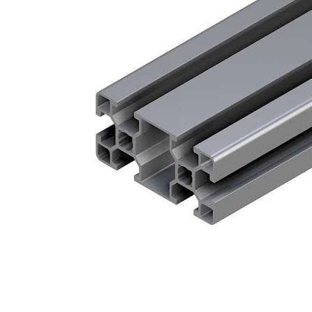
Accurate measurements prevent wasted material, poor fit, and delays during assembly. Careful planning also helps each profile, connector, panel, and accessory arrive in the correct size. Before ordering MiniTec Aluminum Framing, designers should record the full footprint, equipment dimensions, load requirements, access space, and every mounting point that affects the finished structure.
Start With the Available Floor Space
Floor measurements establish the maximum length and width of the frame. Technicians should measure the usable area rather than relying only on building drawings, since columns, drains, conduit, curbs, and nearby machines may reduce the actual space. Clearance around doors, walkways, emergency equipment, and service panels must remain open after installation.
Ceiling height deserves equal attention for tall guards, enclosures, and vertical supports. Overhead pipes, lights, cable trays, ventilation ducts, and sprinkler heads can interfere with a design that appears suitable at floor level. Recording these obstacles gives the designer a clear boundary for the MiniTec extruded aluminum framing layout.
Measure the Equipment the Frame Will Support
Machine dimensions should include more than the main body. Protruding motors, handles, control boxes, hoses, doors, and service covers often extend beyond the listed equipment size. Inspectors should measure the equipment at its widest, deepest, and tallest points, then note which sections move during operation.
Maintenance access also changes the required frame dimensions. Removable covers may need several inches of clearance, while drawers, swing doors, and sliding components require space along their full travel path. Including those movements prevents the aluminum framing material from blocking routine repairs or adjustments.
Record the Required Height of Work Surfaces
Workstation height affects operator comfort, visibility, and reach. Planners should measure the preferred working level for seated or standing tasks, along with the height of fixtures, tools, and products placed on the surface. Adjustable legs may help accommodate several users, but the intended adjustment range must be defined before profiles are cut.
Monitor positions and control panels need separate measurements. Screens should sit within a comfortable viewing range, while buttons and switches should remain easy to reach without stretching. These details guide the placement of horizontal rails and mounting arms within the T slot extrusion structure.
Define the Load and Where It Will Sit
Weight determines profile size, span length, bracing, and connector selection. Engineers should list the weight of equipment, shelves, panels, worktops, stored parts, and any temporary loads expected during use. Dynamic forces from moving machinery, impacts, or vibration may require a stronger design than the static weight suggests.
Load location matters because a centered item affects the frame differently from one mounted near an edge. Cantilevered shelves, monitor arms, and extended fixtures create additional force at their connection points. Clear load measurements help prevent excessive deflection in a T slot aluminum extrusion assembly.
Check Panel Openings and Door Clearances
Guards and enclosures need exact opening dimensions for polycarbonate, wire mesh, sheet metal, or composite panels. Designers should measure the distance between profiles while accounting for panel retainers, gaskets, and mounting clips. A panel cut to the outside frame dimension will usually be too large for the intended opening.
Door measurements must include hinges, latches, handles, and the direction of travel. Swing doors need open floor space, while sliding doors require room along the frame. Proper clearances keep access panels from striking nearby equipment or binding against the extruded aluminum T slot profiles.
Locate Every Attachment Point
Mounting points for sensors, controls, shelves, brackets, feet, and casters should appear on the project drawing. Installers need the distance from a known reference edge rather than rough visual estimates. Precise locations allow the supplier to cut profiles and prepare holes that align with the equipment.
Floor anchors require similar planning. Measurements should show where base plates will sit and whether the concrete contains joints, drains, embedded utilities, or damaged areas. Moving an anchor slightly may affect the full frame width, so those conditions should be identified early.
Account for Connectors and Profile Dimensions
Overall frame size is not always the same as cut length. Corner brackets, joining plates, end fasteners, feet, and caps may add to or reduce the final dimensions. Each connection method should be considered before ordering an aluminum framing kit. Profile width also changes the open area inside the structure. Replacing a narrow rail with a larger one may strengthen the frame but reduce space for equipment or panels. Detailed drawings should identify the selected profile series so every dimension reflects the actual components.
Plan for Cables, Air Lines, and Utilities
Electrical cords, network cables, pneumatic tubing, and vacuum lines need defined routes through or along the frame. Project teams should measure connection locations on both the equipment and the building supply. Extra space may be necessary for cable bends, plugs, filters, regulators, and maintenance access. Utility routing can influence rail placement. Channels in MiniTec Aluminum Framing support clips, covers, and cable-management accessories, but crowded paths can make repairs difficult. A few carefully placed measurements often prevent wires and hoses from crossing doors, work surfaces, or moving parts.
Leave Room for Future Changes
Production equipment often changes after the first installation. Designers may reserve extra profile length, open slots, or unused mounting space for later sensors, shelves, and guards. Modular construction makes additions easier, yet the original frame still needs enough physical room for those updates. Expansion allowances should remain practical rather than excessive. Oversized structures use more material and may interfere with nearby operations. Balanced measurements give the frame enough flexibility without wasting floor space.
Turn Field Measurements Into a Clear Order
A complete order should include a dimensioned sketch, profile lengths, load information, panel sizes, accessory locations, and preferred connection methods. Photographs of the installation area can clarify obstacles that drawings may miss. Consistent units and labeled reference points reduce confusion between the person measuring the site and the team preparing the components.
MiniTec Solutions provides MiniTec Aluminum Framing, compatible hardware, and modular parts for custom industrial structures. Supplying the company with accurate dimensions and operating details helps produce a frame that fits the space, supports the equipment, and arrives ready for efficient assembly.